 In the last few conferences I’ve attended, I was asked by a few of you how I got headphones to work with my Canon 5D Mark II, when it seemed like there was no other components so, as promised, here’s a quick write up.
Shown here with my 5D are:
Sennheiser HD280 Pro Monitoring Headphones
I’m running Canon firmware 2.1.2 (current as of Oct 2012) and Magic Lantern v2.3.
Note: Should you follow my guide, all care, but absolutely no responsibility shall be taken. This is for educational purposes only.
Well, first up, I went and got myself a Fiio E6.
It’s a highly regarded, very portable headphone amplifier, measuring 41w x 40l x 9d mm (about 1.6″ square x 0.4″) and weighs a paltry 16grams (about 0.5oz), that only costs about $30/£20/€25.
This little amp is brilliant, both for its size and cost, it was cheap enough for me to butcher it for my needs without Aus Storage Wife having to worry.

But the first thing about it that didn’t bode well was the clip, it’s on the wrong angle, it’s pretty easy to break (although Fiio do include a spare in the box) and it’s not as secure as I’d like attached to my camera:

The second thing was that the buttons and switches rattled, which when recording with a fairly sensitive microphone, isn’t what you want.
The last was that it didn’t include a cable which would plug straight into the cameras AV jack.
So, here’s what I did to solve those problems:
First task was to crack the little blighter open, a fairly easy task with the side of a razor blade, working the edges slowly, it’s only a little “super glue” like substance around the edges and came apart without much force.
Don’t get me wrong, I don’t think it’d fall apart from normal use, but it didn’t strain me. Cute huh? I wonder what it wants be when it grows up?


On the right showing the battery (golden gumstick), the PCB with mini-usb on the left and the 2 x 1/8″(3.5mm) input and output jacks.
Next up was to breakout my trusty old soldering iron and very carefully remove the SMT 3.5mm INPUT jack (please note, I’m a check twice kinda guy, I almost took of the output jack, but checked twice)
You will note how close the soldering pads for the jacks are to the other components; I had to file down my smallest soldering tip to a very fine point to do it. Lucky I have spares.
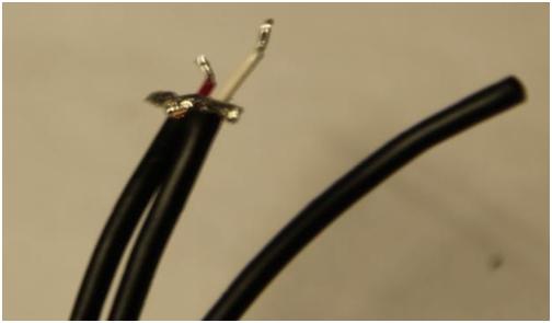
Then it was time to chop up the original Canon AV cable, which Canon were nice enough to make the cable colours Red (Right)/White (Left) Audio and Yellow (Video), as seen on the picture on the right.
Note also that I left the Video Cable (unstripped) well alone, others I seen have cut this short at the plug, but I may want it later, so it stays!
The Ground I twisted together and the red is shorter than the white to match up with the correct solder pads


The Canon 5d Mark II AV Cable is configured as such:
(note: it’s a 3.5mm TRRS plug)
Tip = Left audio (white)
Ring 1 = video (yellow)
Ring 2 = common sheild
Sleeve = Right audio (red)
I even got out my multi-meter to check that, before hacking off the RCA connectors! 
Headphone sockets are typically TRS:
Tip = Left (White)
Ring = Right (Red)
Sleeve = Ground (Black?)
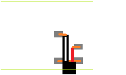
From there, it was soldering time again, I brazed the new cable wires and then soldered them to the pads, you can see my working on paper in the back ground to make sure I don’t stuff it up. Always work to a plan!:

Now, you may be wondering why I didn’t just put a normal headphone plug on the end of the cable and avoid all this? Well, cables get lost in quick pack downs, plugged in the wrong way when stressed and a whole host of other reasons, so the simpler the end solution, the better the result.
Make it easy to use, even if it means a little bit of hard work to get there.
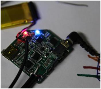
Check to make sure it still works after soldering, not shown on the other end are some alligator clips from an old MP3 player connected to the modified cable to test and cheep headphones to the other… it works:
Then hot glue the new cable to the PCB.

Then I put a dab of soft RTV silicone on the volume switches and the channel of the power switch to stop the rattling, glued it back together, cable tie to keep the 3 cables together and glued on some black button snaps:
Measured the centres of the button snaps for the strap mounting and marked the strap:


Used my old gas powered soldering iron to melt the holes for the new black button snaps (shown with snaps):
Note, I used my soldering iron, because, although the button snap kit came with a whole punch, I find webbing frays over time, the iron melts the webbing making it strong around the hole.


And we’re done!:
Shown in the middle with my little Sony IEM’s for those times when I don’t want to stand out like a

Discussion
No comments yet.